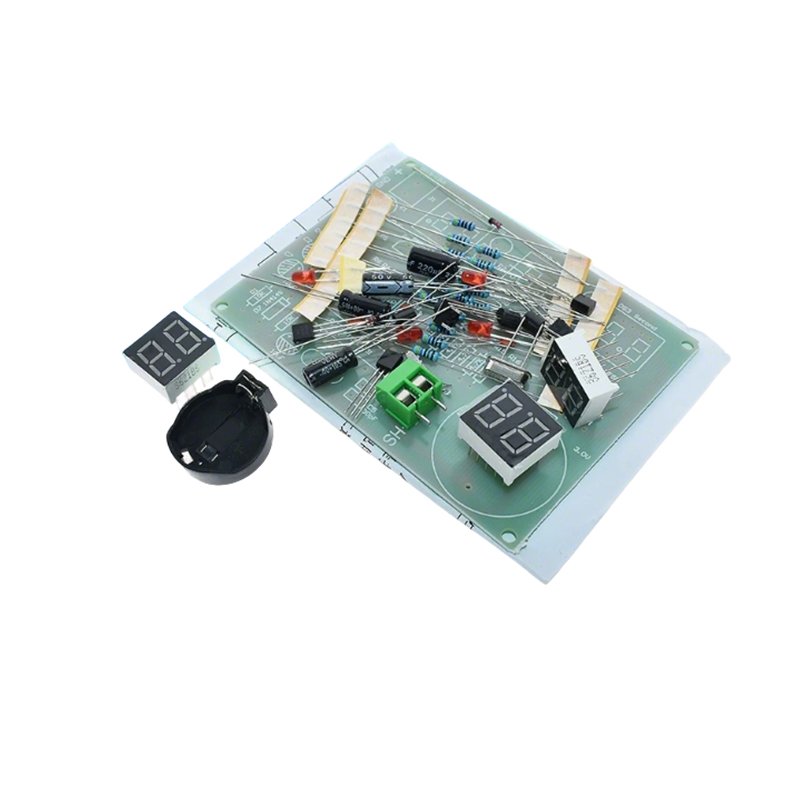
AT89C2051 Microcontroller Digital Clock DIY Kit is an excellent electronic practice assembly kit for students and electronic enthusiasts. The kit adopts AT89C2051 microcontroller with pre-programmed clock firmware, no extra programming needed after soldering.
- The PCB circuit design is reasonable and aesthetically pleasing, with uniform and tidy wiring, and clear and clean silkscreen.
- The circuit board is a 1.6mm thick FR-4 fiberglass board, which is hard and has thick copper foil, making it difficult for the copper to peel off during soldering.
- The AT89C2051 microcontroller already has the clock program written in it, ready to use after soldering without debugging, and keeps accurate time.
- Components are individually bagged, using thick plastic film for heat sealing, so they will not fall out during transportation.
- Each package comes with the schematic diagram, PCB layout, and component list.
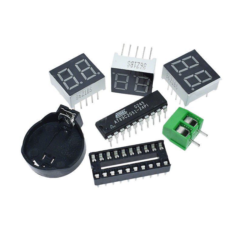
- This six-digit digital clock kit uses the AT89C2051 control chip and three 0.36-inch dual-digit red common-anode LED displays. The display is clear and bright. Because it uses a scanning display method, the a, b, c, d, e, f, g pins of each digital tube are connected in parallel via the bus. Changing the resistance values of R1-R7 can adjust the display brightness.
- The S1 button is used to calibrate the time. Press and hold for more than 2 seconds to enter time calibration mode, switch the segment, and exit. Quick presses are used to adjust the time values.
- This circuit includes a 3V backup battery slot. When the power is off, the microcontroller is powered by the backup battery, so the clock continues running, but the digital tube does not display. When power returns, the backup battery becomes inactive. The chip is powered by an external power supply, and the digital tube displays normally. You can add a power switch so that you can turn off the power when going out and turn it back on when returning, allowing the clock to display normally and saving electricity. Batteries are not included, buyers need to prepare separately.
- Tip: If the digital tube cannot display normally, please disconnect the power, remove the backup battery, then reinstall it and power it on again to restore normal operation.
- Operating Voltage: DC 6–12V, Recommended Voltage: DC 9V
- Backup Battery: Button Battery CR2032 (3V)
- Operating Current: 35mA (Powered by External Power Supply)
- Standby Current: 1.2mA (Powered by Backup Battery)
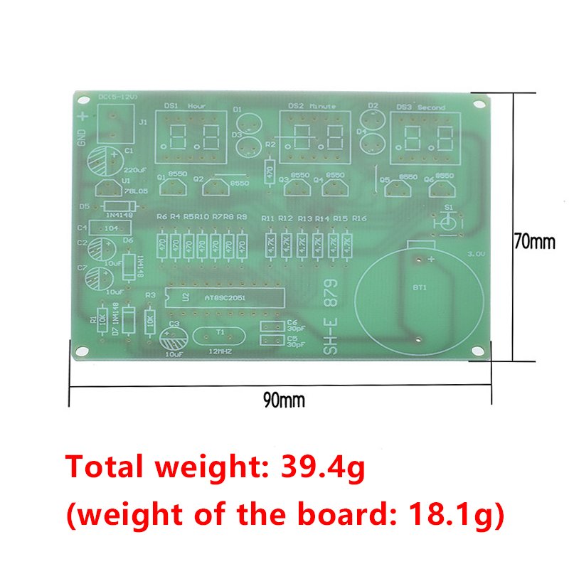
- PCB Material Specification: FR-4, 90*70mm, Thickness 1.6mm, Double-sided UV Green Oil
- Digital Tube: 0.36 inch, 2-digit common anode LED
- Provide the schematic diagram, PCB layout, and component list. The AT89C2051 microcontroller has already been programmed.
- If you want to make it convenient to assemble, you can freely remove or elevate the LED digital tube and solder it to the PCB using a 40 single-row round-hole socket. This kit does not include this socket, so you need to purchase it yourself!
- Follow the diagram to assemble; no debugging is needed, and the success rate is high. Suitable for students in vocational schools and electronic enthusiasts to make.
📏 Size & Weight
PCB Dimension: 90mm × 70mm
Total weight: 39.4g (PCB weight: 18.1g)
Kind reminder: If there are version differences or images not been updated, please refer to the actual product.