YF-7 Dual Channel Time Delay Relay Module
📌 Product Overview
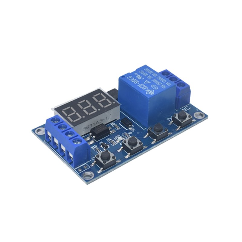
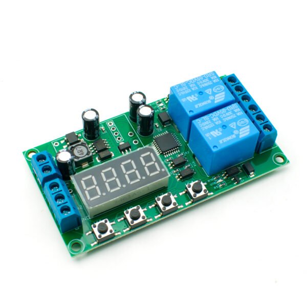
YF-7 dual-channel digital timing relay module is a multi-function programmable timing control board with dual independent relay outputs, built-in 4-digit digital display and 4 operation buttons for parameter setting. It supports wide voltage power supply, DC 7~30V universal voltage and AC 110V~250V power input optional. The timing range covers 0.01 seconds to 999 minutes with high timing precision, equipped with 2 groups of 10A relays, each relay has independent normally open & normally closed contacts, maximum load current 6A. It integrates up to 47 working modes, covering trigger delay, power-on delay, cycle timing, self-locking, signal cumulative timing, interlock control of two relays and other industrial control logic, widely used in solenoid valve drive, street light timing, LED screen control, instrument automatic test and automation equipment.
⚙ Core Product Specifications
- Product Name: Dual-channel Time Delay Relay Module
- Model: YF-7
- Working Temperature: -40℃ ~ +85℃
- Input Voltage: DC 7~30V / AC 110V~250V
- Relay Load Capacity: 10A 250VAC / 10A 30VDC, load within 6A recommended
- Timing Range: 0.01s ~ 999min, adjustable decimal time units
- PCB Dimension: 87mm * 47mm
- Net Weight: 44g
- Housing: Without outer shell
- Remote Control: Not equipped with remote control
- Display: 4-digit digital tube real-time timing display
- Operation Keys: 4 independent setting buttons (Setting, Time+, Time-, Unit Selection)
- Relay Quantity: 2 channels, each with Common, Normally Open, Normally Closed terminals
📍 Terminal Definition
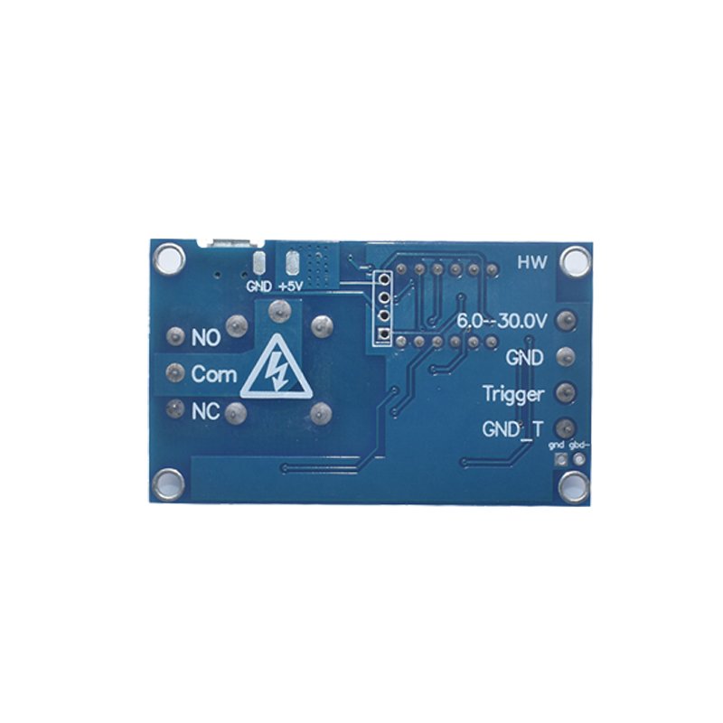
Power & Signal Terminals
- Power Positive: Main power supply positive pole
- Power Negative: Main power supply negative pole
- Signal 1: Channel 1 trigger signal input
- Signal 2: Channel 2 trigger signal input
Relay Output Terminals
- Channel 1: Common 1, Normally Open 1, Normally Closed 1
- Channel 2: Common 2, Normally Open 2, Normally Closed 2
⏱ Decimal Time Unit Rules
- X.XX: Hundredths decimal, timing range 0.01s ~ 9.99s
- XX.X: Tenths decimal, timing range 0.1s ~ 99.9s
- XXX: No decimal point, timing range 1s ~ 999s
- XXX.: Units decimal, timing range 1min ~ 999min
🧩 47 Built-in Working Modes (Core Logic)
- P11 Jog Trigger: Relay pulls in when signal exists, cut off when signal disappears
- P12 Self-locking: One trigger signal closes relay, another signal cuts off relay
- P13 Single Trigger Delay: Signal triggers relay to work fixed time, invalid re-trigger during delay
- P14 Cumulative Timing Trigger: Re-trigger resets timing countdown during working period
- P15 Cumulative Timing Without Reset: Trigger accumulates timing without reset
- P16 Power-off Delay Trigger: After signal input, relay delays power-off for fixed time
- P17 Power-on Delay Start: Relay starts timing after power on, cut off after set time
- P21 Delay Pull-in: Relay acts after fixed delay when signal arrives
- P22 Long Signal Trigger: Relay only acts when signal lasts longer than set time
- P23 Signal Disappearance Delay: Relay starts timing after signal disappears
- P28 Infinite Cycle Mode: Alternate pull-in & cut-off loop after power-on
- P45 Dual Relay Sequential Control: Relay 1 works A time, then Relay 2 works B time sequentially
- P47 Dual Relay Interlock: Relay 1 triggers first, Relay 2 starts timing after Relay 1 finishes And other 30+ industrial timing modes for diverse automatic control demands
🎛 Button Operation Instructions
- K1 (Setting Button): Long press over 1s to enter setting menu to avoid false trigger
- First long press K1: Display P-XX, select working mode via K2/K3, adjust parameter unit via K4
- Second long press K1: Display A001, adjust first timing parameter A by K2/K3, decimal unit via K4
- Third long press K1: Display B001, adjust second timing parameter B by K2/K3, decimal unit via K4
- Fourth long press K1: Return to standby mode (screen displays “—-“)
- K2 (Time+): Increase timing value / switch mode upward
- K3 (Time-): Decrease timing value / switch mode downward
- K4 (Unit Selection): Switch decimal time unit; under standby mode, short press to turn screen on/off and enter low power mode
✨ Product Advantages
✅ Dual independent relay output: Two channels can be controlled separately or interlocked, flexible control logic ✅ Ultra-wide voltage compatibility: DC 7-30V & AC 110-250V dual power supply standards, adapt multiple power supplies ✅ High precision digital timing: 0.01s minimum step, maximum 999 minutes timing, 4-digit digital real-time display ✅ Rich 47 programmable modes: Cover power-on delay, trigger delay, cycle timing, self-locking, dual-channel linkage and other scenes ✅ Complete relay contacts: Each relay leads out COM/NO/NC terminals, meet normally open and normally closed control needs ✅ Industrial grade reliability: Wide working temperature -40℃~+85℃, stable performance for long-time continuous operation ✅ Compact PCB size: 87*47mm lightweight design, easy to install in control boxes and equipment cabinets ✅ Anti-misoperation setting: Long press setting button to prevent accidental touch trigger
🛠 Application Scenarios
- Street Light & Lighting Automatic Timing Control
- Solenoid Valve, Water Pump, Air Pump Timing Switch Control
- LED Display Screen, Advertising Light Timing Power Management
- Laboratory Instruments, Testing Equipment Automatic Cycle Test
- Smart Home Automatic Equipment Timing Switch
- Small Industrial Automation Control Circuit
- Motor Forward & Reverse Sequential Delay Control
- Security Equipment Timing Alarm Trigger
⚠ Important Notes
- The maximum load of each relay is 10A, it is recommended to control load below 6A to extend service life.
- DC and AC power cannot be connected at the same time, only single power supply input is allowed.
- When inductive loads (solenoid valve, motor) are connected, freewheeling diode is suggested to protect relay contacts.
- Do not short-circuit power terminals, avoid burning the main control chip.
- The module has no outer shell, install it in sealed control box to prevent dust and short circuit.