📌 Product Introduction
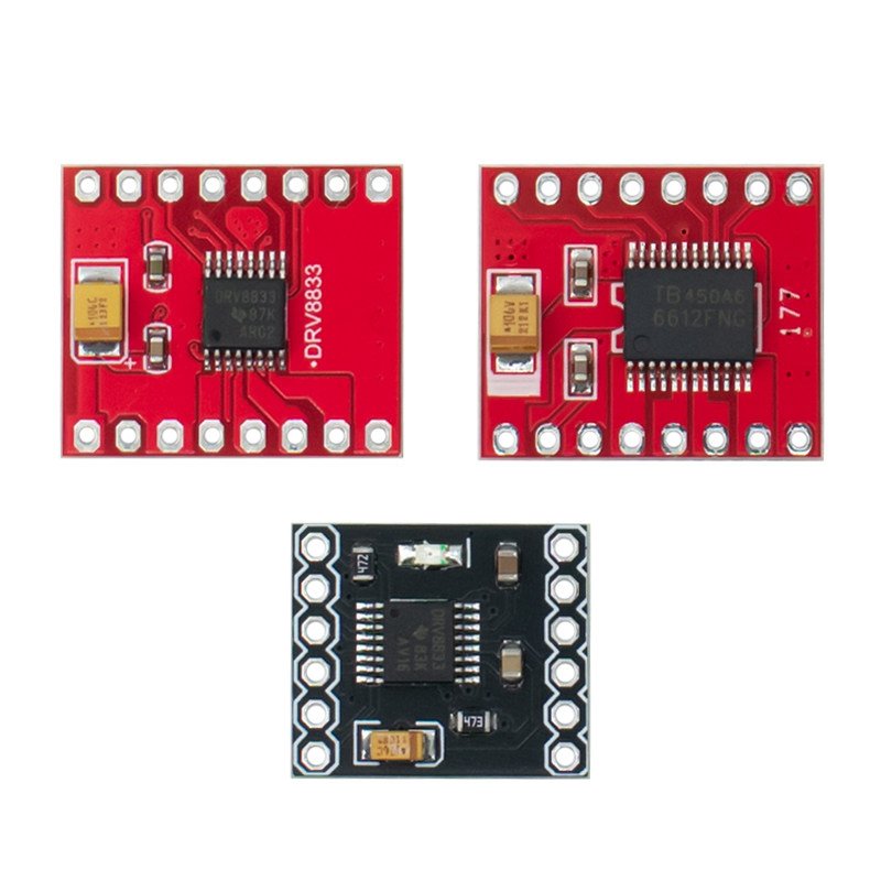
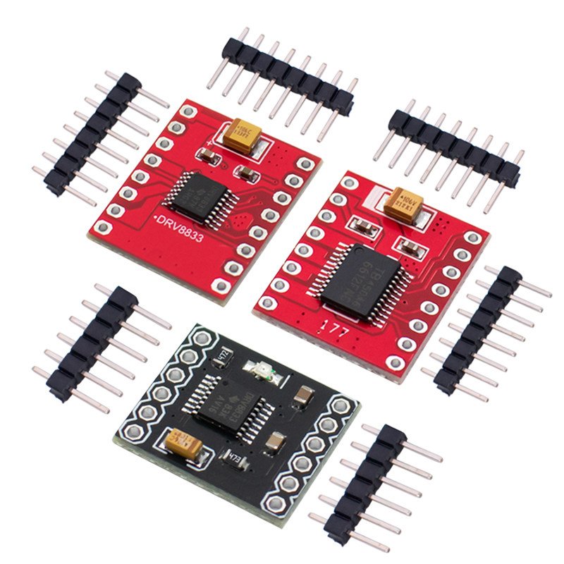
We provide two optional versions: TB6612FNG module/DRV8833 module/DRV8837 module, both adopt genuine original chips, specially designed for maker projects and electronic design competitions. Compared with traditional L298N driver modules, they feature smaller size, higher energy efficiency and lower heating.
✅ Core Advantages
• Dual-channel H-bridge driver, supports independent control of two DC motors
• Compact PCB layout, high integration, easy to embed into robotic projects
• Built-in multiple protection circuits: overcurrent, short-circuit, undervoltage lockout and thermal protection
• Support PWM speed regulation, control motor forward, reverse and stop
• Low power sleep mode available
• Easy wiring, compatible with mainstream microcontrollers such as Arduino, STM32
📋 Parameter Specification
TB6612FNG Module
- Logic Input Voltage(VCC): 3.3V ~ 5V
- Motor Operating Voltage(VM): 4.5V ~ 12V
- Continuous Output Current: 1.2A per channel
- Peak Current(Single Pulse): 3.2A
- Drive Channels: 2 Channels
DRV8833 Module
- Input Voltage Range: 2.7V ~ 10.8V
- Continuous Output Current: 1.5A per single H-bridge
- Drive Channels: 2 Channels
- Compatibility: Pin-to-pin alternative for TB6612 module
📌 Pin Definition & Operation Guide
TB6612FNG Module Pins
- VM: Motor power supply
- VCC: Logic level power supply (3.3~5V)
- GND: Common ground
- STBY: Standby pin, High = Enable driver, Low = All motors stop
- AIN1, AIN2: Direction control for Motor 1
- PWMA: PWM speed control for Motor 1
- A01, A02: Output terminals connect to Motor 1
- BIN1, BIN2: Direction control for Motor 2
- PWMB: PWM speed control for Motor 2
- B01, B02: Output terminals connect to Motor 2
Control Logic Truth Table
| Motor Channel |
INx1 |
INx2 |
Status |
| Motor 1/2 |
0 |
0 |
Stop |
| Motor 1/2 |
1 |
0 |
Forward Rotation |
| Motor 1/2 |
0 |
1 |
Reverse Rotation |
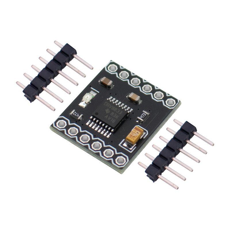
DRV8837 Single/Double Channel Motor Driver Module
The DRV8837 series includes single-channel and dual-channel H-bridge motor drive modules.
✅ Single Channel Version
Size: 15 * 20MM
Input Voltage: 1.8V-7V
Single H-bridge Output Current: 1.8A, can drive 2 DC gear motors.
Built-in overcurrent protection, short-circuit protection, undervoltage lockout, and overheat protection.
With low-power sleep mode.
Application: This product can drive DC motors under 1.8A and 4-wire stepper motors.
Pin Definition
- IN1: PWM input 1 of chip A, voltage range: -0.3-7V
- IN2: PWM input 2 of chip A, voltage range: -0.3-7V
- OUT1: Motor drive output 1 of chip A, voltage range: -0.3—7V
- OUT2: Motor drive output 2 of chip A, voltage range: -0.3—7V
IN1 and IN2 form one H-bridge output port, connected to the two terminals of a DC motor.
- SLEEP: Low level puts chip A to sleep, high level for normal operation, built-in pull-down resistor to GND, Voltage range: -0.5 — 7V
- VCC: Chip power supply pin, voltage range: 1.8 — 7V
- GND: Ground
- VM: Motor power supply pin, voltage range: 1.8 — 11V
✅ Double Channel Version
Size: 20 * 22.5MM
Input Voltage: 1.8V – 12V
Single H-bridge Output Current: 1.8A, can drive 2 DC gear motors.
Built-in overcurrent protection, short-circuit protection, undervoltage lockout, and overheat protection. Comes with low-power sleep mode.
Application: This product integrates two chips and can drive two DC motors under 1.8A and 4-wire stepper motors.
Pin Definition
- INA1: A chip PWM input 1, voltage range: -0.3-7V
- INA2: A chip PWM input 2, voltage range: -0.3-7V
- INB1: B chip PWM input 1, voltage range: -0.3-7V
- INB2: B chip PWM input 2, voltage range: -0.3-7V
- OUTA1: A motor drive output 1, voltage range: -0.3—7V
- OUTA2: A motor drive output 2, voltage range: -0.3—7V
- OUTB1: B motor drive output 1, voltage range: -0.3—7V
- OUTB2: B motor drive output 2, voltage range: -0.3—7V
INA1 and INA2 are one H-bridge output port, connected to the two terminals of a DC motor.
INB1 and INB2 are the second H-bridge output port, connected to the two terminals of another external DC motor.
- SLEEPA: Low level puts chip A to sleep, high level is normal operation, includes a pull-down resistor to GND. Voltage range -0.5 — 7V
- SLEEPB: Low level puts chip B to sleep, high level is normal operation, includes a pull-down resistor to GND.
HW-048 TB6612FNG Motor Driver Module Blue Board
The TB6612FNG compact motor driver board features two H-bridges and can control up to two DC motors, with a maximum continuous drive current of 1.2A per channel (startup peak current up to 2A/3.2A). The AIN and BIN signals can be used to control the motor in four modes: forward/reverse/brake/stop. The motor can rotate at any speed via PWM signal input, with PWM signals up to a frequency of 100kHz.
Module Dimension: 21.46mm * 19mm
Pin Description
The motor driver board has 16 pins.
- VCC: Logic power supply, 5V
- VM: Motor drive voltage, 5V~13.5V
- GND: Ground. The three GND pins are mutually connected on this module.
- AIN1, AIN2, BIN1, BIN2: Control motor forward and reverse rotation
- AO1, AO2: Connect to Motor 1
- BO1, BO2: Connect to Motor 2
- PWMA, PWMB: Signal input for PWM speed regulation
- NC: Not connected
Logic Control Table
| AIN1 |
AIN2 |
BIN1 |
BIN2 |
PWMA |
PWMB |
Working Status |
| 1 |
0 |
1 |
0 |
1 |
1 |
Forward rotation |
| 0 |
1 |
0 |
1 |
1 |
1 |
Reverse rotation |
| 1 |
1 |
1 |
1 |
1 |
1 |
Free brake |
| X |
X |
X |
X |
0 |
0 |
Brake |
The module supports connecting to Arduino mainboard via jumper wires, and uses TTL level signals to control motor rotation direction and speed. We provide ready-to-use Arduino test program for quick development.
- Please strictly distinguish power supply pins and pay attention to positive and negative polarity during wiring. Wrong wiring may burn the module.
- Do not exceed the rated voltage and current to avoid damage.
- These modules are precision driver boards; operate carefully if you are new to electronic projects.
- DRV8833 can directly replace TB6612 with almost full pin compatibility.
📌 Application Scenarios
Smart robot car, balance car, small DC geared motor drive, 4-wire stepper motor control, maker prototype development, electronic competition projects.